The Magic Formula Tire Model
Tires are complex systems that are indispensable to the vehicle. Tires connect the vehicle with the road through four relatively tiny patches, through which a tire determines how a vehicle behaves while, for example, cornering, accelerating or braking. In other words, tires have considerable influence on the dynamics of vehicles, accounting for its complexity as a system for generating forces and moments.
Tire’s complexity and importance demand comprehensive study and research so that a better understanding of the dynamics of vehicles is achieved. For the sake of investigation and assessment of tire behavior, Engineers use modeling and simulation techniques. Thus, it is important to build tire models that are accurate in predicting the forces and moments generated by the tire. Modeling of tires is not straightforward. Tires are very complicated systems; indeed, they do not have a known specific unique physical model. Many engineers and organizations have come up with numerous tire models. Some examples are the Magic Formula, Fiala, F-Tire, CDTire, RMOD-K, TAME Tire and many more, each of which follows a distinct methodology and approach.
1) Tire Forces & Moments:
The tire generates three forces and three moments. The three generated tire forces are the longitudinal force Fx , the lateral force Fy and the vertical force Fz . The three generated tire moments are the overturning moment Mx , the rolling resistance moment My and the self-aligning moment Mz . In the following subsections we’ll discuss two tire forces, the longitudinal force and the lateral force, and one moment, the self-aligning moment.
The slip is one of the most important elements in tire dynamics. The slip components are the longitudinal slip, the lateral slip and the turn slip, the first two types are the most common in tire dynamics studies. These slip quantities are responsible, among other factors, for the generation of the tire forces and moments.
a) Longitudinal Slip and Force
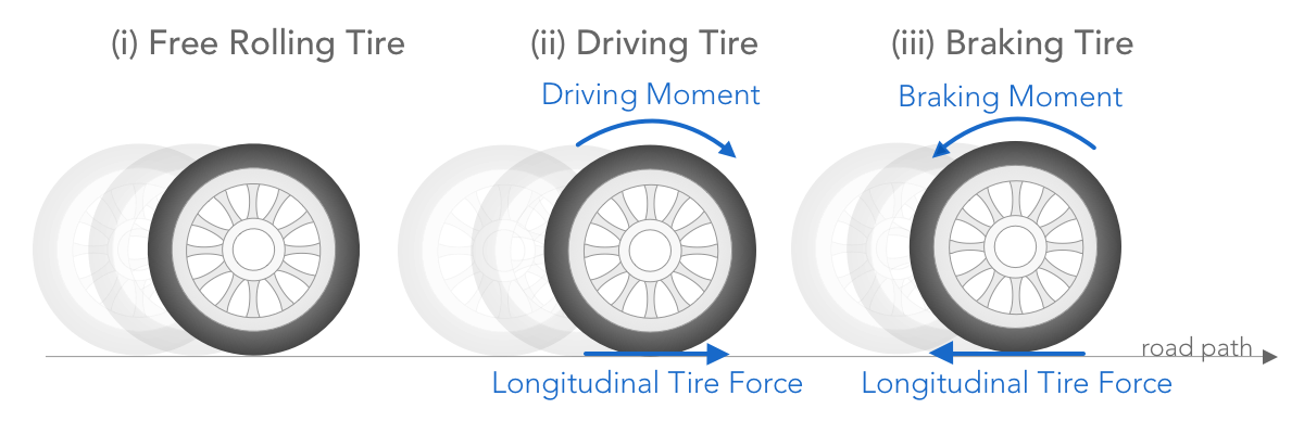
When a driving or a braking moment is applied to the wheel rotating axle, longitudinal slip is generated. This longitudinal slip is one factor that contributes to the generation of the longitudinal force, which provides the necessary traction or braking force to accelerate or stop the vehicle. To put it simply, while accelerating or braking, a longitudinal slip is present, and thereby a force will be generated, called the longitudinal force Fx, pointing in the direction of travel when accelerating, and pointing opposite to the direction of travel when braking. A distinction between a freely rolling tire, an accelerating and a braking tire is shown in the figure below.
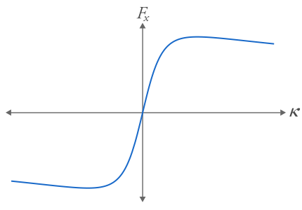
the longitudinal force Fx is generated due to the longitudinal slip. The steady state behavior of the longitudinal force varies nonlinearly with the longitudinal slip. A graph showing the steady state behavior of the longitudinal force against the longitudinal slip is shown below.
b) Lateral Slip, Lateral Force and Self-Aligning Moment
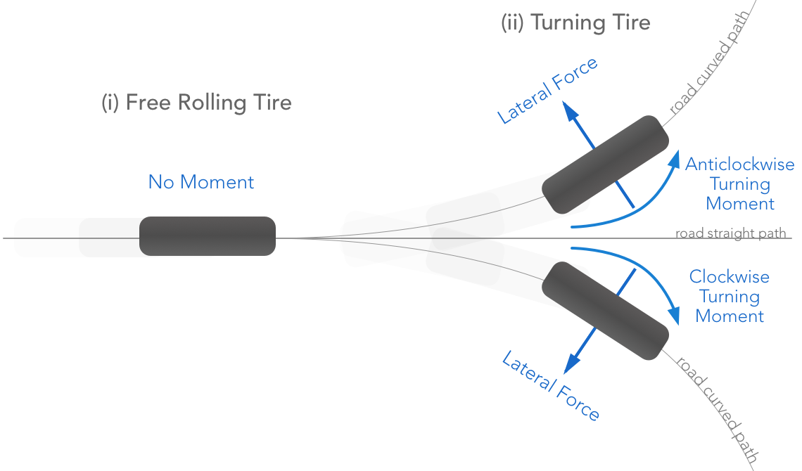
The lateral slip, or slip angle, α of the tire has a significant implication on the vehicle cornering behavior. The lateral slip is one factor that produces lateral tire force, which assists the vehicle while cornering. For a free rolling tire moving in a straight line, no lateral slip, or slip angle, is present; this is because the direction of the contact point’s velocity vector and the direction of the wheel/tire to which it is heading are the same. Once a turning moment is applied to the wheel axle, the wheel turns to a direction different from that of its contact point’s velocity vector. Therefore, a lateral slip is present in the situation of an applied turning moment. An illustration representing the relation between the application of a turning moment and a lateral force is shown below.
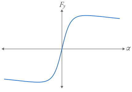
Lateral force, or cornering force, results from the lateral slip ς,or slip angle α. The behavior of the lateral force is similar to that of the longitudinal force. The steady state behavior is shown in the following figure with respect to the variation of α.
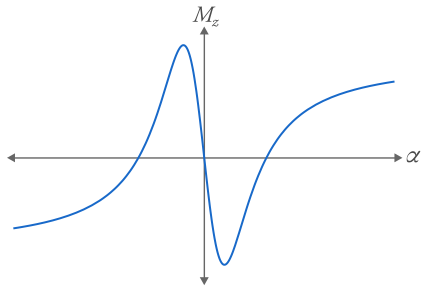
The self aligning moment is a function of the lateral slip. The following diagram depicts the relationship between the self-aligning moment Mz and the slip α.
c) Combined Slip
In the last two scenarios, the slip is called pure slip since it is the only present slip; that is, longitudinal or lateral slip. On the other hand, if both types of slip are present in one scenario, the slip is called combined slip. For example, when a driving or braking moment is applied on a wheel/tire that is also taking a turn, both longitudinal slip and lateral slip is present.
In the presence of both the longitudinal slip and the lateral slip, both the the longitudinal and lateral forces are present. This situation is known as combined forces, resulting from combined slip. A parametric graph that shows the impact of α on the forces is shown below.
2) The Magic Formula Tire Model:
In order to study the behavior of the tire, it is essential to have accurate mathematical models. There are numerous tire models available, each of which follows a specific approach. Two main approaches of devising tire models are the physical approach and the empirical approach. Models that follow the physical approach are called physical models, and models that follow the empirical approach are known as empirical models. By considering the best of both worlds, the hybrid approach comes to life; it is used to design semi-empirical (semi-physical) models. This classification is illustrated below with specific examples of tire models belonging to each category.
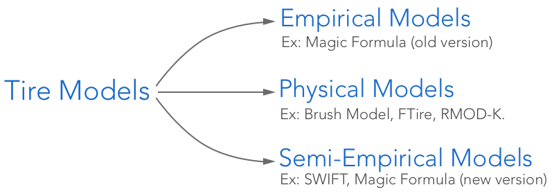
Empirical models are mathematical formulas that describe certain characteristics of the tire. These mathematical equations are obtained through extensive experimentation and testing. With the aid of empirical models, one could accurately represent the dynamical behavior of the tire without having a computationally expensive physical model. An example of such empirical models is the Magic Formula.
The Magic Formula is an empirical tire model that is used in many vehicle dynamics simulations. It produces the nonlinear steady state forces and moments of the tire with great accuracy. The Magic Formula equation governing the nonlinear behavior of the forces and moments is written in its simplest form as follows:
$$ \mathscr{F}(x) = D\sin\left(C \arctan(Bx-E(Bx-\arctan(Bx)))\right) $$There are four parameters or factors that influence the shape of the resulting curvature. These factors are $B$: stiffness factor, $C$: shape factor, $D$: peak factor and $E$: curvature factor. By using specific values for the $B$, $C$, $D$ and $E$ factors, the Magic Formula, represented by last equation, produces the longitudinal tire force, the lateral tire force and the self-aligning moment. Three sets of values for the coefficients of the Magic Formula used to produce the lateral force, the longitudinal force and the self-aligning moment curvatures are shown in the following table.
| Forces & Moments | B | C | D | E |
|---|---|---|---|---|
| Longitudinal Force | 0.171 | 1.690 | 4236 | 0.619 |
| 0.210 | 1.670 | 6090 | 0.686 | |
| 0.214 | 1.780 | 7711 | 0.783 | |
| Lateral Force | 0.244 | 1.500 | 1936 | -0.132 |
| 0.239 | 1.190 | 3650 | -0.678 | |
| 0.164 | 1.27 | 5237 | -1.610 | |
| Self-Aligning Moment | 0.234 | 2.680 | -48.56 | -0.460 |
| 0.164 | 2.460 | -112.5 | -2.04 | |
| 0.127 | 2.410 | -191.3 | -3.21 |
Note that, the coefficients B, C, D and E are functions of the normal force Fz, the friction coefficient μ, the inflation pressure and even the temperature. In other words, the numerical values given in table 1 are just an approximation of the four parameters. These factors affects the overall shape of the resulting force or moment curve. So, by varying each parameter we can form the desired look of the curve, and hence the tire characteristics. This is normally done by optimization methods in order to calibrate the model against measurements.
To sum up, we've demonstrated the magic formula tire model and its mathematical equation. Also, the coefficients B, C, D and E were presented. Various values, in table 1, were given to generate the different forces and moments of the tire force. Last, the nonlinear steady state behavior of the longitudinal force, the lateral force and the self-aligning moment were illustrated in fig.2, fig.4 and fig.5, respectively.